
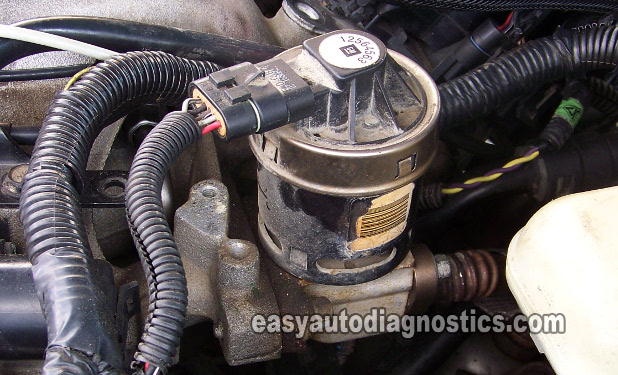
Testing and troubleshooting an EGR valve issue or EGR diagnostic trouble code (DTC) on your GM vehicle is not hard to do.
In this article, I'll show you how to do it step-by-step and you won't even need a scan tool!
Before we jump in head long into this article, you need to know that there are two types of electronic EGR valves that GM uses in most of their late model vehicles.
The EGR valve that's covered by this article are for 3.1L, 3.4L, and 3.5L GM vehicles from 2000 to 2009 models years (although some late 1999 models use this type of EGR valve too). To make sure this tutorial applies to your specific vehicle, check this section out first: Identifying The EGR Valve.
Contents of this tutorial:
- Symptoms Of A Bad EGR Valve.
- What Tools Do I Need?
- Circuit Descriptions Of The GM EGR Valve.
- TEST 1: Is The Intake Manifold Clogged?
- TEST 2: EGR Pintle Position Sensor Test.
- TEST 3: EGR Pintle Position Sensor (Road Test).
- TEST 4: EGR Pintle Position Sensor 5 Volt Reference Circuit.
- TEST 5: EGR Pintle Position Sensor Ground Circuit.
- TEST 6: Testing The EGR Pintle Solenoid.
- TEST 7: Intake Manifold Blocked With Carbon.
- Identifying The EGR Valve.
- Where To Buy The EGR Valve And Save.
- More GM 3.1L, 3.4L V6 Tutorials.
 You can find this tutorial in Spanish here: Cómo Probar La Válvula EGR Electrónica (3.1L, 3.4L GM) (at: autotecnico-online.com).
Symptoms Of A Bad EGR Valve
I can tell you from experience that a bad EGR valve is rare. I'm not saying they don't go bad (they do), but it's rare.
The most common problem is the EGR passages inside the intake manifold's plenum getting clocked with carbon. This design (either by intent or incompetence on the part of GM -after all, Ford and other makes don't have this problem) has made auto repair shops tons and tons of money (before someone sues me, let me tell you that this is just my opinion).
OK, whether the EGR valve itself is bad or the passages are clogged with carbon, this is what you'll usually see:
- Check engine light (CEL) will be shining nice and bright.
- EGR valve fault codes:
- P0401 EGR System Flow Insufficient.
- P0403 EGR Solenoid Control Circuit.
- P0404 EGR Open Position Performance.
- P0405 EGR Position Sensor Circuit Low Voltage.
- Rough idle.
- Really bad gas mileage.
- Lack of power as you accelerate the vehicle down the road.
- Car (or truck or mini-van) seems to run OK above 30 miles and hour but once you come to an idle, the engine barely stays running.
- The car runs great, just the check engine light (CEL) is on and with EGR codes stored in the PCM's memory.
What Tools Do I Need?
You'll need the following:
- A multimeter (don't have a digital multimeter? Need to buy one? Click here to see my recommendations: Tekpower TP8268 AC/DC Auto/Manual Range Digital Multimeter (Amazon affiliate link)).
- A repair manual.
- For whatever remove and replace info you'll need that is not covered by this article.
- A wire-piercing probe to pierce the wire.
- If you need to see what this tool looks like, click here: Goupchn 4mm Banana to Banana Plug Test Leads Kit (Amazon affiliate link).
Circuit Descriptions Of The GM EGR Valve
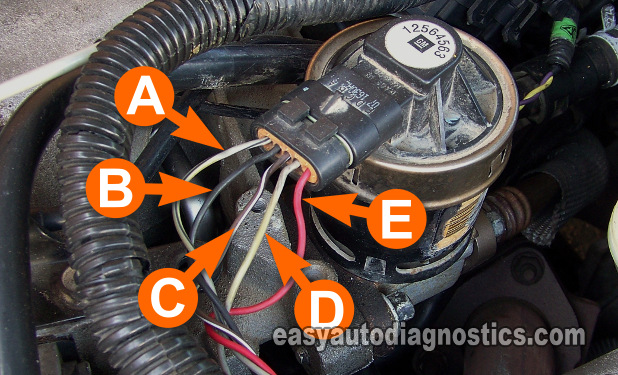
There are 5 wires sticking out of the EGR valve's connector, in this section we'll explore what each one does.
Most of the EGR valves will have the letters A thru' E molded onto the EGR valve's connector. I'll be using these same letters for the circuit descriptions below:
- Circuit labeled A:
- Ground circuit for EGR valve solenoid. Gray with black stripe wire.
- Circuit labeled B:
- EGR valve pintle position sensor Ground (provided by the PCM). Black wire.
- Circuit labeled C:
- EGR pintle position signal circuit. Brown with white stripe wire.
- Circuit labeled D:
- 5 Volt Reference for pintle position sensor (provided by the PCM). Gray wire.
- Circuit labeled E:
- Power source for EGR solenoid (provided by the PCM). Red wire.
The color of the wires described in the circuit descriptions above, are the colors for the majority of the GM vehicles that use this type of EGR valve, so there's a good chance that on your car, these wires may not share the same colors.
If on your vehicle the color of the wires are different, no need to worry. This is no cause for concern since the circuit descriptions are still the same.
TEST 1: Is The Intake Manifold Clogged?
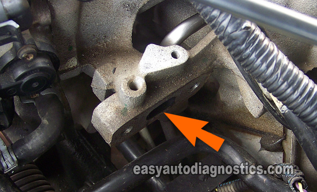
The very first thing that we'll do, is to see if the intake manifold plenum's EGR passages are clogged since this is the most common problem with this type of EGR valve set up.
This is what you'll need to do:
- 1
Remove the EGR valve from the intake manifold.
If the engine in your vehicle has been running for any length of time, the EGR valve will be HOT, be careful.
If the engine is hot, let it cool down before attempting the tests in this article. - 2
Have a helper start the engine (with the EGR valve off of the intake).
- 3
The engine will do one of two things:
1.) The engine will start and idle normally, as if the EGR where still in place.
2.) The engine will idle very high and may stall. - 4
If the engine does idle extremely high, have your helper turn off the engine immediately.
Let's interpret your test results:
CASE 1: The engine idled very high and/or stalled. This indicates that the EGR valve passages inside the intake manifold are NOT clogged.
This is the normal and expected result when the EGR valve passages are not clogged. Since this test has confirmed that the EGR passages (inside the intake manifold) are not clogged, the next step is to check the pintle position sensor that's inside the EGR valve. Go to TEST 2.
CASE 2: The engine idles normally. This indicates that the EGR valve passages inside the intake manifold are clogged.
The next step will be to remove the intake manifold's plenum to clean the EGR valve's passages. In TEST 7: Intake Manifold Blocked With Carbon, I've got some tips and suggestions (and photos) as to what it looks like when these passages are clogged with carbon.
TEST 2: EGR Pintle Position Sensor Test
The EGR valve has a pintle position sensor that tells the PCM how much the EGR valve's pintle has opened.
With this information, the PCM can control the exact amount of exhaust gas recirculating back into the engine's combustion chambers.
In this test, we'll check that the EGR valve is producing the correct position signal voltage with the key ON and engine OFF.
Now, since you're coming from TEST 1, go ahead and re-install the EGR valve back to its place on the intake manifold's plenum.
IMPORTANT: This test is done with the EGR valve connected to its electrical connector. You'll need to use a back probe or a wire piercing probe to access the signal within the wire. You can see an example of this tool (and where to buy it) here: Goupchn 4mm Banana to Banana Plug Test Leads Kit (Amazon affiliate link).
When ready, this is what you'll need to do:
- 1
Select Volts DC mode on your multimeter.
- 2
Connect the red multimeter test lead (with an appropriate tool ) to the wire labeled with the letter C.
This is the wire that provides the pintle position to the PCM. - 3
Connect the black multimeter test lead to a good Ground. Preferably directly on the battery negative (-) terminal.
- 4
Now, turn the key ON, but engine OFF (KOEO) and observe the Volts reading on your multimeter.
- 5
The multimeter should display 0.6 to 0.9 Volts DC.
Let's see what your multimeter test result means:
CASE 1: Your multimeter displayed 0.6 to 0.9 Volts DC. So far so good, since this is the normal reading and confirms that the EGR pintle is not stuck open.
The next step is to see if the pintle position sensor produces the correct voltage while the EGR valve is in action. For this test, go to: TEST 3: EGR Pintle Position Sensor (Road Test).
CASE 2: Your multimeter DID NOT display the indicated voltage. It displayed a LOWER or no voltage. This usually indicates a problem with the power circuit of the EGR valve.
More specifically, it usually means that the EGR valve pintle's position sensor is not getting power (5 Volts) or that the sensor is bad. Go to: TEST 4: EGR Pintle Position Sensor 5 Volt Reference Circuit to further investigate this.
TEST 3: EGR Pintle Position Sensor (Road Test)
In this test step, you're gonna' check that the EGR valve is actually opening and closing.
You'll easily accomplish this by road testing the vehicle with your multimeter connected to the pintle position signal Wire of the EGR valve (which is the wire labeled with the letter C).
You'll need to use 2 long jumper wires to connect the multimeter leads (from inside your vehicle) to the EGR valve:
- The red test lead of the multimeter has to connect to the signal wire on the EGR valve.
- The black multimeter test lead has to connect to a good Ground.
This way, you'll be able to read the multimeter from inside the vehicle, since the multimeter leads are not long enough to reach inside the vehicle.
If you haven't already, re-install the EGR valve back to its place on the intake manifold's plenum.
Now, it's never a good idea to drive while being distracted, so I recommend that you have a helper reading the multimeter as you drive (or vice-versa).
OK, here's what you'll do:
Part 1
- 1
Connect the red multimeter test lead to the wire (circuit) labeled with the letter C, with a long wire that can reach from inside the vehicle to the engine compartment.
NOTE: The jumper wire has to be long enough so that whomever is helping you read the multimeter, inside the car, can do it comfortably. - 2
Connect the black multimeter test lead to a good Ground point with another jumper wire.
You can Ground the test lead either inside the passenger compartment or directly on the battery negative (-) post. - 3
Start the vehicle and let it idle.
It's important that the engine be at normal operating temperature (or this test will not work). - 4
Your multimeter should display a voltage reading between 0.6 to 0.9 Volts DC.
Part 2
- 5
Start driving when everything is set up and ready and the engine is at normal operating temperature.
- 6
Every time you accelerate the vehicle, your assistant should notice the 0.6 to 0.9 voltage DC reading go up.
Depending on how much and how hard you accelerate the car, the voltage may go up to about 4 to 4.5 Volts.
The key here is to see the base voltage go up. There's not a specific number you're looking for, so don't worry if this number doesn't go up all the way to 4.5 Volts. - 7
As soon as you let go off of the accelerator pedal, the reading on the multimeter should drop back to down to the initial voltage reading you observed at idle.
The above test checks two very crucial functions of the EGR valve which are: 1) the EGR valve pintle position sensor and 2) the EGR solenoid. Both of these components make up the EGR valve. OK, here are the test interpretations:
CASE 1: Your multimeter displayed 0.6 to 0.9 Volts DC which increased as you accelerated the vehicle. This is the correct test result and it lets you know that the EGR valve is good and that you have an intermittent problem on your hands.
Intermittent problems are hard to solve, since if they're not present and causing the problem (when you test them), there's nothing that can be done to solve them. The only suggestion is to wait a few more days and retest.
CASE 2: Your multimeter displayed 0.6 to 0.9 Volts DC which DID NOT increase when you accelerated the vehicle. This result indicates one of two things: 1.) That the solenoid inside the EGR valve is bad or 2.) the pintle position sensor is bad. To further test this, go to: TEST 6: Testing The EGR Pintle Solenoid.

